June 18, 2020
Author: Daniel Seitz, Coherent, email: Daniel.Seitz@coherent.com, www.coherent.com
Growing Demand for 3D Marking
The laser marking market is characterized by an increased need to mark or texture non-flat surfaces, such as curved, inclined, and stepped surfaces as well as free-form objects and recessed surfaces. Unfortunately, traditional laser markers and integrated machines are limited to a flat planar field of view that can be adapted for simple inclined planes or cylindrical surfaces by rotating and moving the part during marking. However, the only way to accommodate more complex shaped surfaces was to resort to the cost and complexity of programmed robotics or complex 5 axis machines.
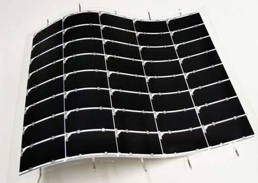
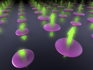
But now an automated “smart” solution, called SmartMap 3D, has been developed by Coherent that combines novel hardware and software, specifically a proven fast variable focus method, a novel 3D machine vision, all under the control of powerful marking software (Visual Laser Marker). This easy to use combination not only simplifies the entire process, it also eliminates the cost and time of implementing precision fixturing, clamping or placement. (The software also supports simpler marking applications including marking on the fly.) In this article, we describe the main features and benefits of this cost-effective approach to 3D marking which is available in both marking sub-systems and complete machines. Moreover, because it is independent of laser type, SmartMap 3D can be used to produce all the various types of laser marks (e.g., color change, engraving), precision surface treatments like roughening and structuring, and even the latest black marking of stainless steel products using ultrashort pulse (USP) lasers – see figure 1. It is now available with all Coherent laser markers and complete marking machines.
Laser Marking – Versatility & Other Advantages
Laser marking is a widely used versatile process in many industries that can be optimized to create permanent high-contrast marks on virtually any material type. The marks can be used for product identification and tracking, for anti-counterfeit brand protection, or for functional (e.g., fiducials) purposes. There is also a fast-growing demand to produce aesthetic marks such as brand logos (e.g., computer tablets) and particularly for decorative marks and unusual textures in automotive parts such as trim components, dashboards and associated buttons, gear shift sticks, and tail light details.
The exact requirements of a particular marking task vary tremendously between
different applications, but in most cases, manufacturers want to produce a permanent mark, and often, one that is difficult to deliberately alter or counterfeit. This makes the laser far superior to inkjet or pad printing. In addition, for many food and beverage applications and with some medical devices and pharma products, the mark may come into contact with material that is to be ingested or placed directly within the patient’s body. Again, this precludes old fashioned ink marking. Another common requirement is that the marking process not adversely affect surrounding (unmarked) material and underlying layers, and that minimal or no post processing (e.g. cleaning) be required. By matching the laser power, wavelength, and pulse width to the absorption and thermal characteristics of the target materials, this spatial selectivity is relatively straightforward for laser marking, even for high-resolution marks.
Laser marks can be generally classified according to whether they involve removal of surface material (engraving) by laser ablation, or material color change. Material removal can be simple engraving or involve the selective removal of a coating or layer of paint. The color change can be a simple process like localized charring of food cartons using an infrared laser, or a color change such as darkening of white plastics such as titanium dioxide impregnated ABS used in kitchen appliances by means of an ultraviolet laser, or it can involve changing the color of a plastic additive with a visible or ultraviolet laser, or foaming used to create white marks on colored polymers, and more recently it may take the form of “black marking” of certain metal surfaces using USP lasers – see figure 1. Coherent manufactures all these lasers and over a wide range of power levels and can fully evaluate and optimize any new marking task in the company’s application labs. Coherent can then supply a solution in the form of a standalone laser, a laser marking sub-system, or a complete machine with positioning and automated sorting functions. Moreover, all the laser systems and integrated machines now offer the SmartMap 3D option for simple 3D marking as described below.
Beyond the Limitations of Traditional Systems and Sub-Systems
With the notable exception of mask-based marking using high-energy pulses from excimer lasers, most laser marking is based on scanning a focused laser spot over the surface to be marked, sometimes in combination with continuous or steeped motion of the part(s) being marked. The three main optical components to implement this process are the laser, the dual galvanometer mounted mirrors to perform orthogonal beam scanning in the xy directions, and the beam delivery lens to focus the spot at the correct z distance, i.e., at the work surface – see figure 2 (a). A beam expander also is nearly always attached in front of the laser to support the use of a strong (high numerical aperture, NA) beam delivery lens that delivers a small focused spot with high intensity that maximizes spatial resolution of the marks and maximizes process efficiency, avoiding the need for excessive laser power. The beam delivery lens is usually a f-theta design. Unlike a conventional spherical focusing lens which has a curved focal plane, the f-theta lens is configured to create a flat focal plane so that the focal depth of the laser beam is independent of the position across the lens and hence across the marking surface. This works great for flat surfaces that are perpendicular to the laser beam direction but a shallow depth of focus means it is not suited to 3D marking where the z distance from the focusing lens to the target surfaces varies significantly.
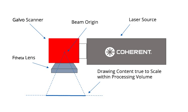
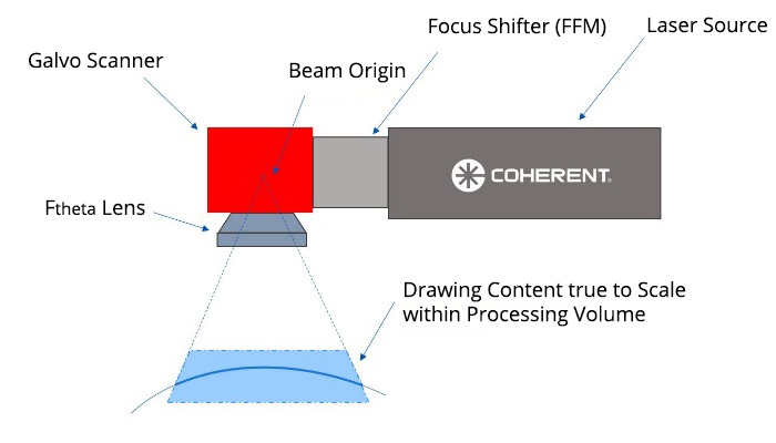
Figure 2. (a) A typical 2D marking set up can create true to scale content over a flat plane. (b) With SmartMap 3D, the use of a focus shifter module (FFM) enables the system to create true to scale marks over a target volume.
To mark 3D surfaces with robotic systems, the delivery optics, and sometimes even the entire laser sub-system, are moved relative to the work surface which may also be robotically moved. This is cumbersome, expensive and requires complex programing and may struggle to deliver the required accuracy for complex graphics and miniaturized characters. SmartMap 3D now provides an alternative solution that is far simpler, faster and more economical because it does not involve moving either the optical system or the part, thanks to the use of a fast focus module placed within the optics – see figure 2 (b). This allows rapid focal length adjustment. Depending upon the particulars of the laser and scan system, a total range of up to ± 130 mm from the nominal focal distance can be accommodated. Combining this z scanning with the xy scanning provided by the dual galvanometers provides the capability to position the focused laser at any xyz location inside a target volume without changing the size or shape of the spot.
SmartMap 3D – Combining Hardware, Software, and 3D Machine Vision
Another key element for simple 3D marking is a user-friendly software option in Visual Laser Marker (VLM) that automatically determines the combination of focus module and galvanometer mirror movements required to produce the mark on a particular workpiece. Based on Coherent’s 40 plus years of experience in laser marking applications, this software defines the surfaces of the workpiece and then stores this for each job type. The user then maps the mark on to the surface via intuitive GUI control. The mark details can be generated and stored using either of two commonly used 3D surface mapping types. The most intuitive method is called projection mapping where the mark is defined as a series of points all on vectors relative to a fixed viewing point. (This is the most intuitive since it matches the creation of the mark using a fixed input laser.) For regular solids such as spheres, cones, and cubes VLM can create uv mappings. Here the mark is defined on a series of 2D (flat) surface segments using orthogonal coordinates u and v. This allows the use of existing mark files such as pdf and dxf documents, and supports flexible content such as QR codes, barcodes and related marks. Various algorithms map these segments on to the real xyz coordinates of the workpiece surface. For complex shaped work pieces or graphics that are wrapped around parts, more sophisticated users may prefer to import the data from their preferred CAD software and then edit this in VLM – many commercial CAD platforms offer this export format.
The 3D viewing capabilities of VLM also provides a fully accurate preview of how the part will look like after marking, and helps to place drawings, visualize the clipping angle in false colors, and even set the movement of the machine’s axes – all from the preview window.
The third part of the SmartMap 3D system is hardware – a machine vision line camera that scans each part before marking. This is available at two different wavelengths to accommodate the reflectivity and color of virtually any markable material. The integration of this vision component allows the smart marking software to detect the shape and orientation of the parts before marking, a three-dimensional point cloud. These results are then compared to the stored CAD model files for that particular part. The degree of matching is given a score, as a percentage. The GUI can optionally display the extent of matching in a false color overlay of the camera image(s). Operation can be automated so that if the overall match exceeds a minimum score, the machine marks the job. This minimum acceptable score is one of several parameters that the user selects in the stored routine for each job type. Alternatively, based on the GUI preview and score, the operator can decide whether to initiate marking or adjust the position/orientation of the workpiece to get a better match. The point cloud can be also converted to 3D surface and directly used in VLM in case no CAD model for the comparison step is available. This is therefore an ideal tool for lot size 1 or job shoppers with no requirement for expensive precision fixturing.
The smart system is able to accommodate different placements of the workpiece without moving the laser or the workpiece, because it takes into account several important parameters, including projection distortion, clipping angle, apex angle, and 3D surface orientation.
Projection distortion. Since the laser beam emanates from a fixed point during the entire process, the scan system must therefore also correct for the geometrical distortions that would otherwise occur during the marking process – see figure 3. This type of distortion correction has been widely employed in the past when working with relatively simple shapes, such as angled flat surfaces and cylinders. But, it becomes substantially more difficult for arbitrary, free-form 3D shapes. The upgraded VLM software now eliminates this challenge by performing all these corrections automatically. Figure 4 illustrates the effectiveness of this software.
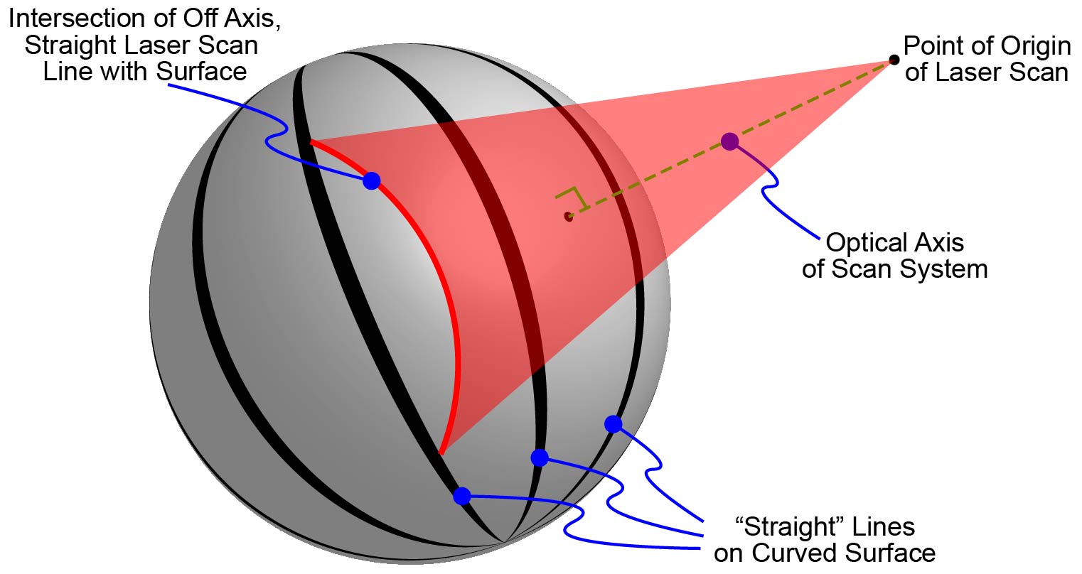
Figure 3. Projection distortion occurs when marking a “straight” line at non-normal incidence on to a curved surface.
Clipping angle. Conventional 2D marking is configured so that the laser beam is always aligned close to perpendicular (±10°C) to the surface of the workpiece, i.e., near “normal incidence.” However, with 3D marking, the laser can mark at angles that vary significantly from normal incidence. The maximum angle that can be employed is determined by the absorption and reflectivity of the workpiece surface and is called the clipping angle. This can be operator selected for each job individually to enable the same laser marker or marking machine to mark different materials.
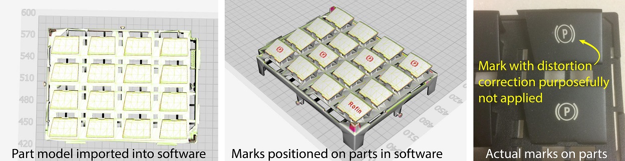
Figure 4. To utilize the SmartMap 3D marking system from Coherent, a CAD model of the part is imported into the software, and the user positions the desired marks on the piece(s). The final results show that distortion correction is necessary to achieve the correct mark geometry on the work piece.
Apex angle. This defines the limits of the marking volume in the xy axes. It is essentially the field of view of the marking optics together with the focal distance of the f-theta lens. The VLM stores this information for every machine or sub-system in which it is installed. It will automatically reject as an error, any operator attempt to mark beyond this physical limit.
Summary
Laser marking offers unique advantages for creating numbers, symbols, logos, and other graphics on virtually any type of material. Until now, most laser marking has been confined to flat surfaces or simple shapes. Marking on free-form shapes was too complex and costly for many potential applications. This has now completely changed; the advent of a smart 3D marking system, SmartMap 3D, brings pushbutton simplicity and automation, unlocking the full potential of laser marking for industries such as automotive, consumer electronics, appliances, and many others.